| feedback.chaosdorf.dn42 | |
|---|---|

| |
| Raspberry Pi Model B Rev 2.0 | |
| Ort | Schleuse |
| Zweck | infodisplay, Türsteuerung |
| OS | Raspbian (Debian) Wheezy |
| Disks | 8GB SDHC"GBSDHC" is not declared as a valid unit of measurement for this property. |
| RAM | 512MB488.281 MiB <br />500,000 kiB <br />512,000,000 B <br />0.477 GiB <br />4.656613e-4 TiB <br /> |
| Swap | 100MB0.1 GB <br />100,000 kB <br />1.0e-4 TB <br /> |
| Admin-Toolkit | Yes |
| ssh key path | ~/.ssh/authorized_keys |
| PAM? | Yes |
| SSH user login? | No |
| Besitzstatus | Club-Eigentum |
| Kontakt | derf |
| Benutzung | Nachfragen |
| Admins | derf |
| MAC address | b8:27:eb:38:93:02 |
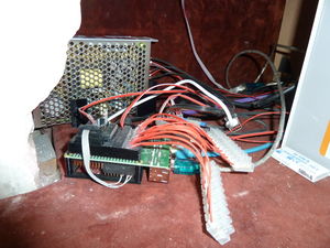
Steuert das Infodisplay und die Clubraumbeleuchtung. Zieht 4W0.004 kW <br />7.72 EUR/Year <br />.
/ ist read-only gemountet, die benutzten Dateisysteme (/srv/www, /tmp, /var/log) jeweils tmpfs.
Dienste
- dorfmap per hypnotoad (Mojolicious) und lighttpd mit mod_proxy. Wird beim Booten nach /srv/www gecloned. Siehe Lichtsteuerung
- Xorg mit nodm und dwm, siehe Infodisplay
- ring_bell per inetd für Türklingel und public/private announcements
Anschlüsse
| Anschluss | Gerät |
|---|---|
| USB | frei |
| USB | frei |
| HDMI | HDMI → DVI Kabel zum Infodisplay |
| microUSB (VCC) | +5V per TSR 1-2450 DC/DC 24V/5V 1A Schaltregler und Chaosdoor 12V-Netzteil |
| LAN | Direktverbindung zum Patchpanel im Serverraum |
| P1:2 (5V0) | Klingel |
| P1:3 (GPIO2) | Optokopplerboard:1 |
| P1:5 (GPIO3) | Optokopplerboard:5 |
| P1:7 (GPIO4) | Optokopplerboard:3 |
| P1:6 (GND) | Klingel |
| P1:9 (GND) | Außenbeleuchtung |
| P1:11 (GPIO17) | Einschaltsignal Außenbeleuchtung |
| P1:12 (GPIO18) | Signal für Klingel |
| P1:13 (GPIO27) | Optokopplerboard:6 |
| P1:15 (GPIO22) | Optokopplerboard:4 |
| P1:18 (GPIO24) | Optokopplerboard:2 |
| P1:25 (GND) | Optokopplerboard |
Optokopplerboard
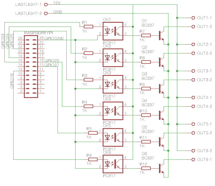
Die GPIO-Pins im Bild stimmen nicht, tatsächliche Inputs siehe oben. 12V-Versorgung kommt aus dem Chaosdoor-Netzteil.
Input n schaltet Output n.
| Anschluss | Kabel | Gerät |
|---|---|---|
| 1 | Doppellitze rot/weiß | LED-Leiste Chaosdorflogo innen |
| 2 | Einzellitze rot/rot | LEDs im Schaufenster per 500mA-Schmelzsicherung und OKI-78SR-5/1.5-W36-C 5V 1.5A Schaltregler |
| 3 | RJ45 blau/weiß | Weiße LED-Reihe Hackcenter |
| 4 | RJ45 grün/weiß | Blauer LED-Streifen Hackcenter (Treppenseitig)(Treppenseitig) |
| 5 | RJ45 gelb/weiß | Weiße Lampe über dem CLC1160 |
| 6 | RJ45 braun/weiß | Blaue Röhre im Hackcenter |
